Final Project: A Working Clock
|
Project Summary
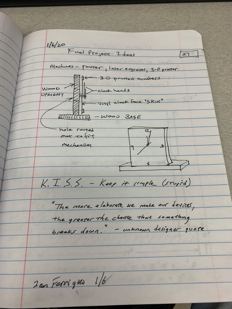
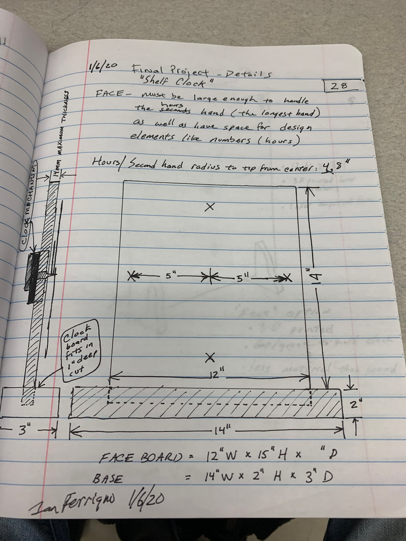
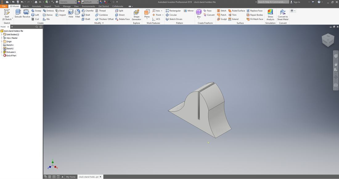
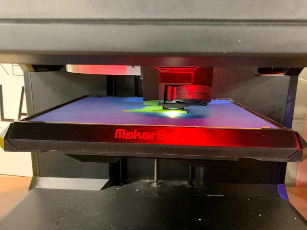
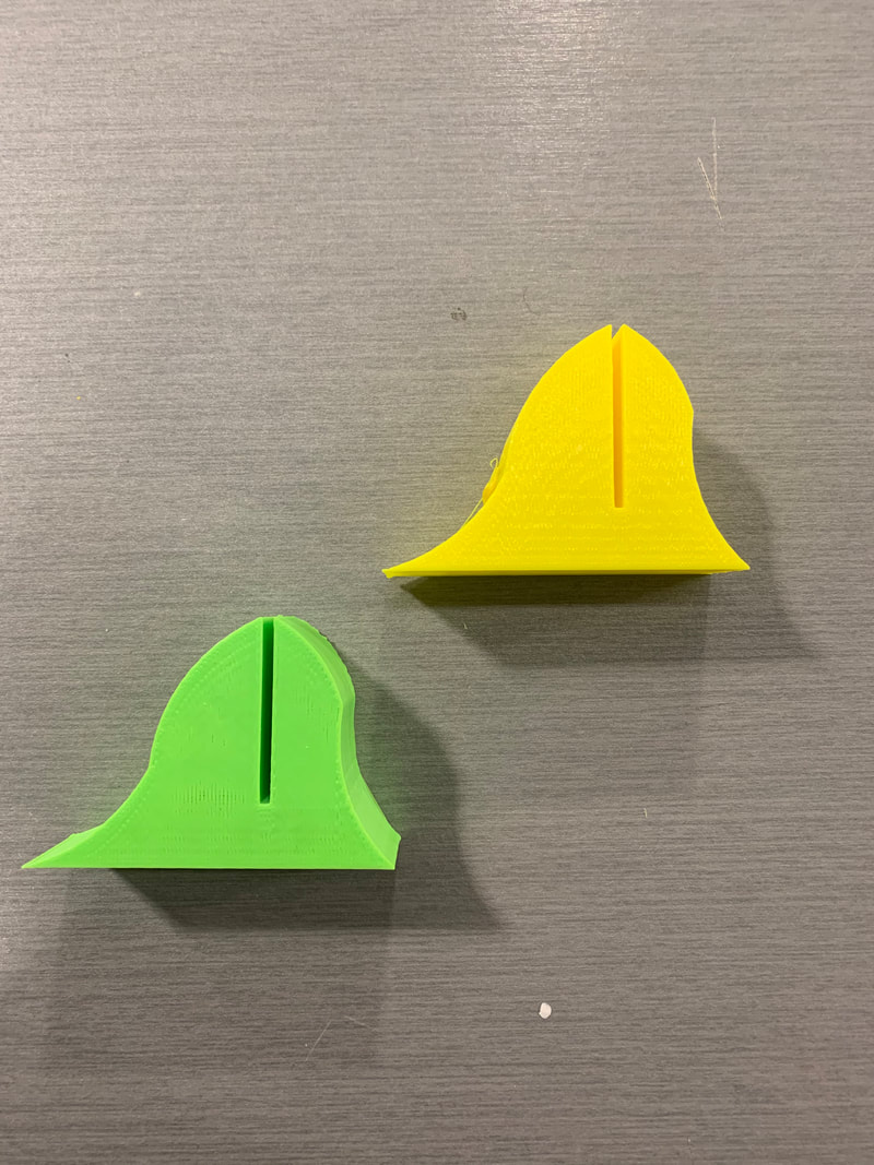
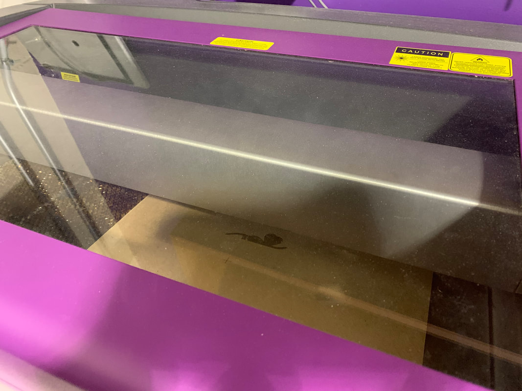
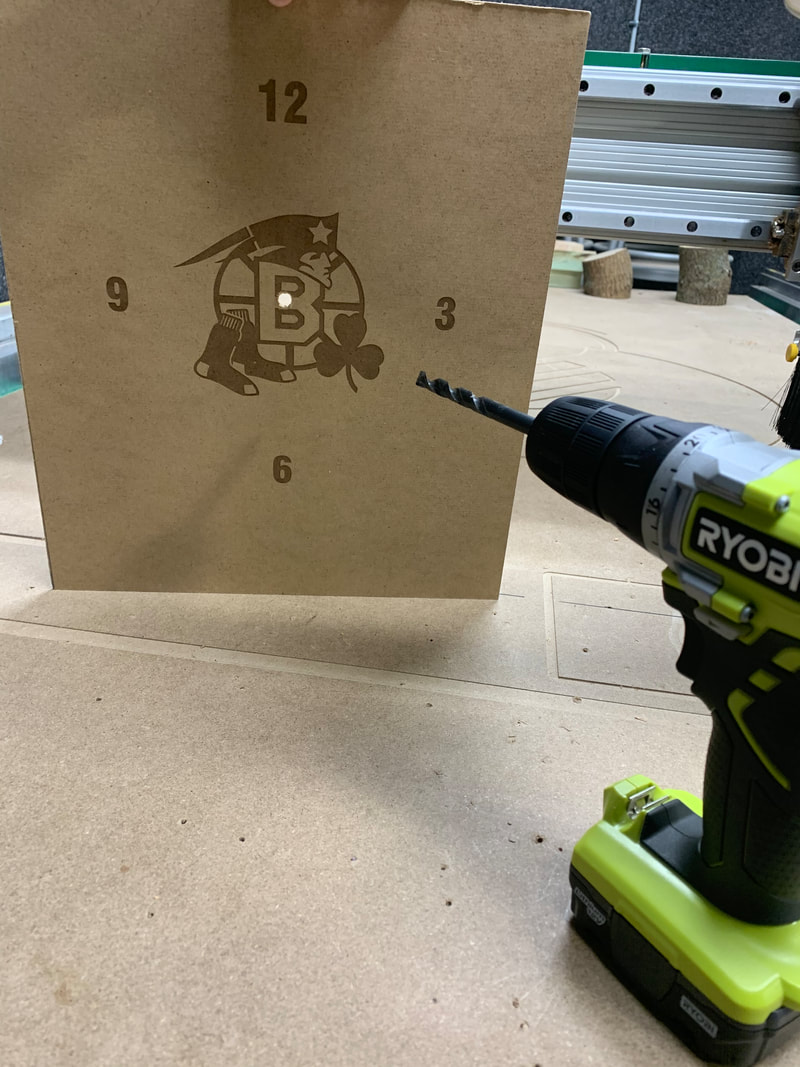
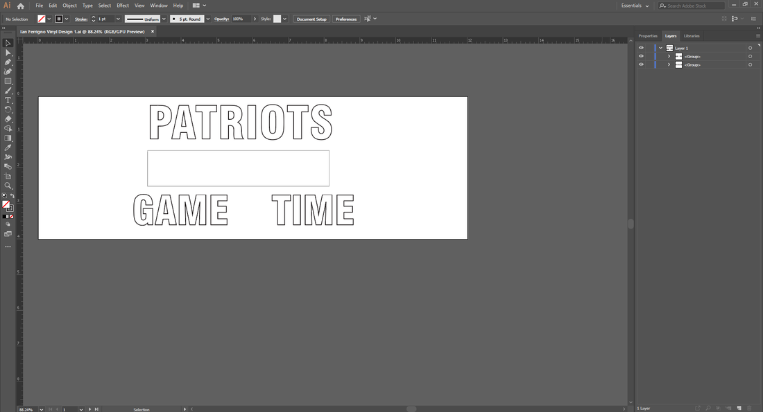
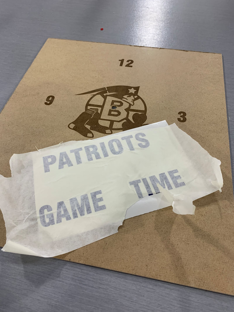
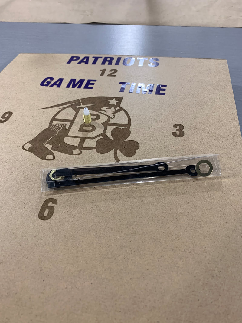
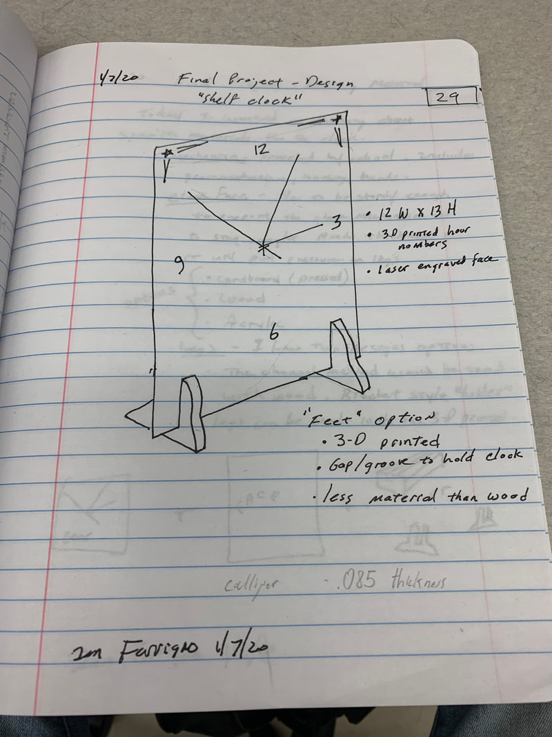
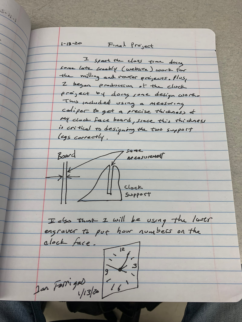
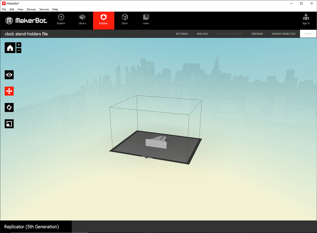
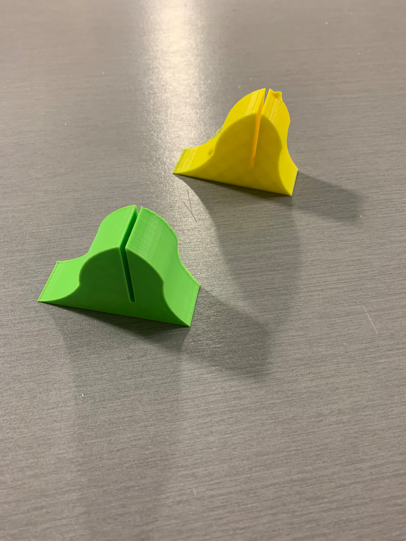
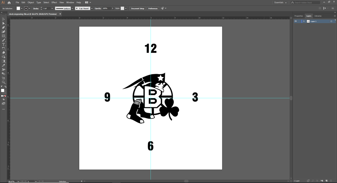
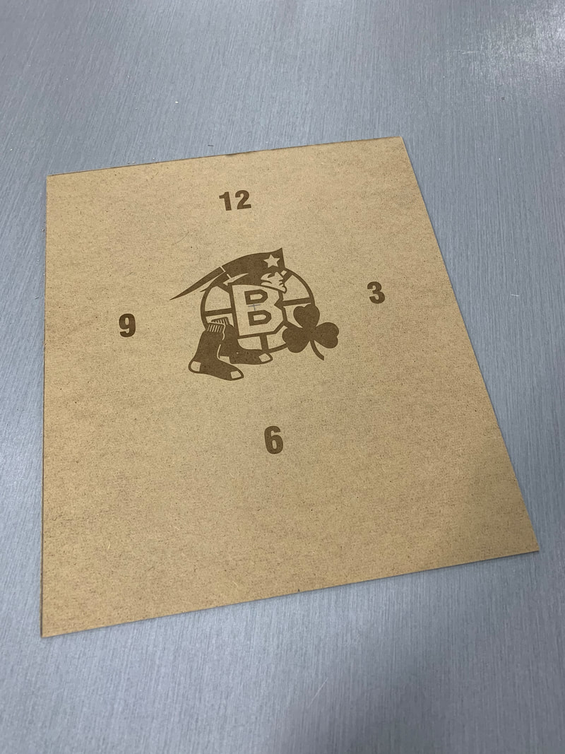
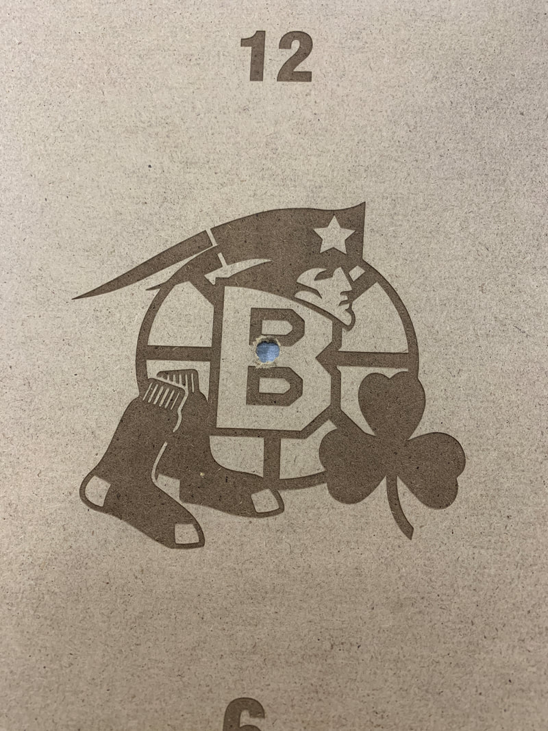
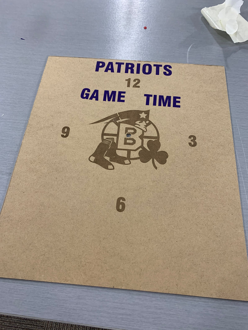
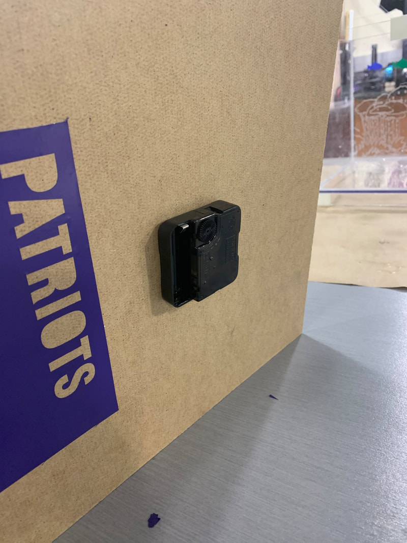
The final project in IDEA was the design and production of a working clock. I was provided a standard three-arm clock mechanism, but other than that all of the remaining design and fabrication was up to me. Coming up with a design was a matter of thinking and jotting down ideas in my designer's diary. Once the design was set, materials were procured and production began. When all of the components were finished, I assembled the final clock. Production Recipe The first step of the entire process was to understand the overall project objective and then start coming up with ideas. I used my designer diary to jot down clock ideas. The set of pictures at the top show my progression from random clock ideas to establishing a clock design and then working on particular details such as the clock legs. Along the way I had to consider the machines I would use and how they would impact production. For example, I had a clock stand design in mind that would be a piece of wood with a routed "channel" in which the clock face would nest. But while thinking through machinery, the idea of using the 3D printer to make clock legs came about. With a design in mind a made a list of the components and materials. There would be a total of four product components: 3D-printed legs (2), a compressed hardboard for the upright face, and the pre-manufactured clock mechanism. Various artistic and finishing elements would complete the clock including laser-engraved hour numbers and primary design on the face, and a vinyl-cut message applied at the top of the face. The latter idea came about well after the design phase and was actually produced in-process. Physical production began with Inventor software where I designed two legs to hold up the clock face board. I transferred the design directly to the 3D printer software interface using a flash drive, and the printer did the rest. The most critical part of the leg production was to get the width of the "channel" in each leg to be the width of the compressed hardboard. A measuring caliper was used to perform this task. The legs are shown in the photos to the right. The next stage of production was where I used Illustrator software to create the clock face design. My plan was to use the laser engraver machine to engrave my design right onto the clock face board as I would have very good control over the design features such as the font for the hour numbers and the specifics of a Boston sports team logo montage I thought up for the center of the clock face. The laser engraver worked as expected and the design looks great. As with the legs, I transferred the design to the laser engraver via a flash drive. In addition to laser engraved artistic elements, I added a text slogan to the face of the clock by way of the vinyl cutter machine. As with the laser engraver, the vinyl cutter provides great control over the finished piece of vinyl. I used transfer tape to apply the phrase "Patriots Game Time" to the top of the clock. The next step was where I used an electric hand drill to create the center hole through which the clock mechanism spindle would fit. Care was taken to make the diameter just large enough to fit the clock arm spindle. Clock Assembly Assembling the clock was a fairly simple operation. First, the two 3D-printed legs were attached to the lower edge of the clock face board. Holding the clock board upright with the legs on a table, and applying firm pressure was enough to seat the face all the way down the leg channels. Now the clock could stand on its own for the next step, which required the use of both hands to complete. This step was attaching the clock mechanism to the board and applying the clock arms to the spindle. With the spindle jutting out through the hole in the board, a couple washers and a slim nut were used to hold the mechanism in place. Then in proper order based on diameters, the hour hand and then the minute hand were fitted onto the spindle. Last came the seconds hand which had a small axle at its' center which fit directly into a center hole in the clock spindle. Before inserting a AA battery to power the clock, the manual clock hand adjustment was used to set the hour and minute arms to the correct time. The clock began telling time immediately upon my inserting the battery into the timer mechanism. Success! Learning Summary Designing and producing a working clock was a great project for capturing all of the things I learned throughout the semester of IDEA. By now I was used to beginning the process with ideation and notes in my diary and once I started on the clock design work I did several pages of the diary in a single session. I came up with the idea to keep the overall clock design as simple as possible to help me out time-wise, and I think it was a wise thing to do. I also learned that a designer must consider materials and machinery during the design process, as adjustments might need to be made. In fact, I made a couple adjustments to the project such as switching the clock base from a channeled piece of wood to creating 3D-printed legs, plus decided to utilize the vinyl cutting machine to produce an artistic element to the clock face instead of producing all of the face's elements via laser engraver. (To be transparent, another requirement of the project was to use at least three machines from the IDEA lab, so machine use was also a factor in decision making.) The final clock looks great. Assembly went exactly as planned because I took my time on the design and planning stages, which at the end of the day was my biggest takeaway from IDEA class. 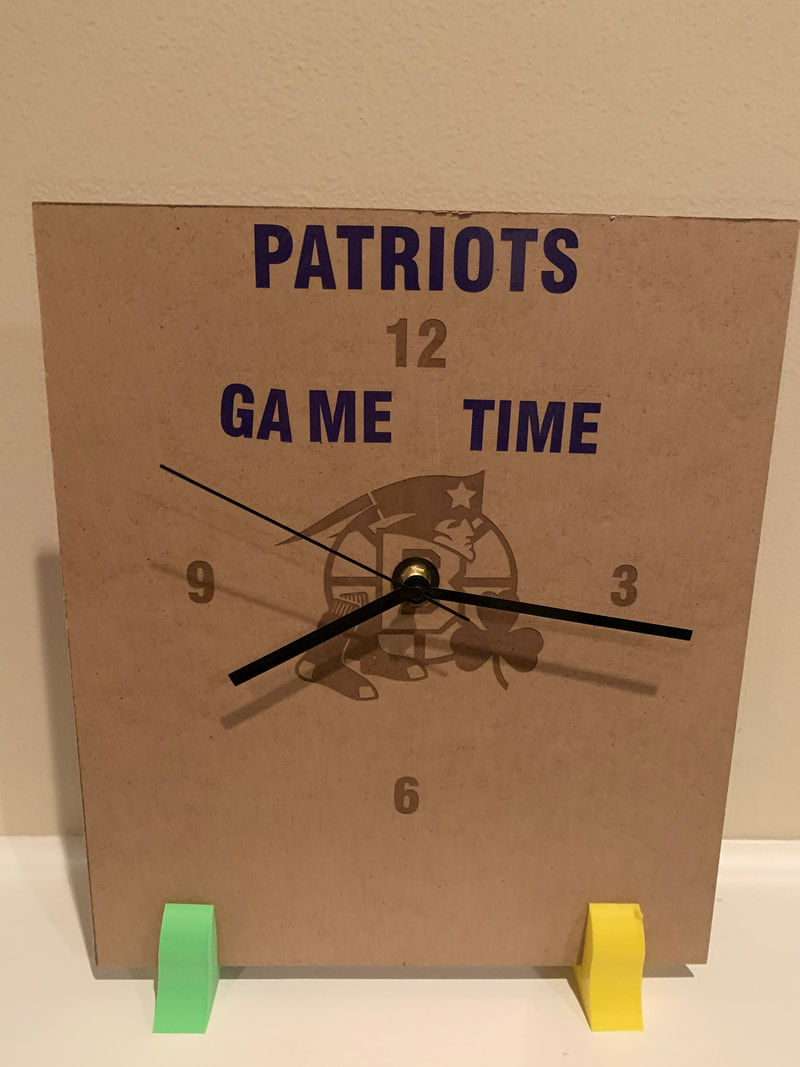
Final
|
|
|
