The Mill Project
|
The Mill project was a first jump into the world of machine tooling. More specifically, it exposed us to the fusion of a design, computer software (as the brains of the operation) and a machine that "tools" the product out of a raw piece of material.
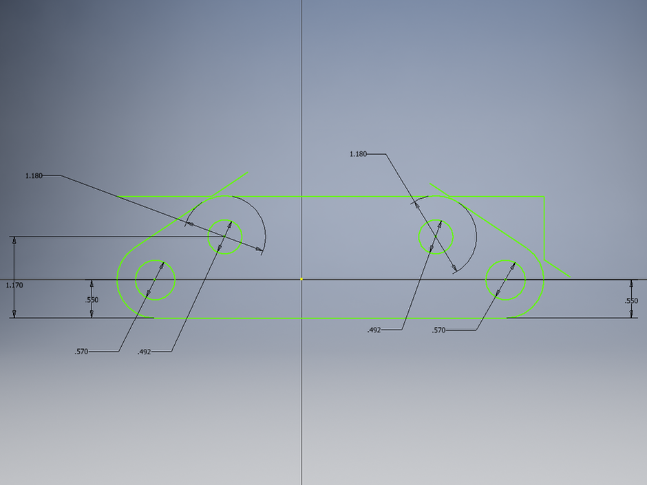
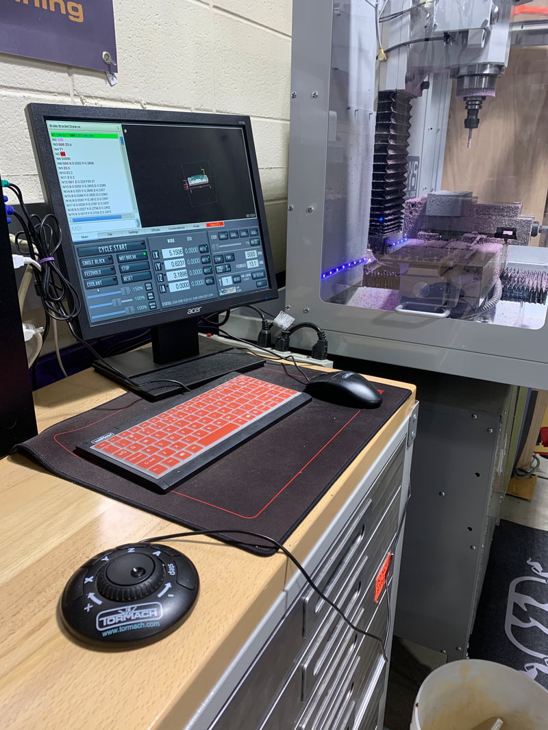
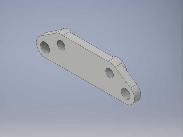
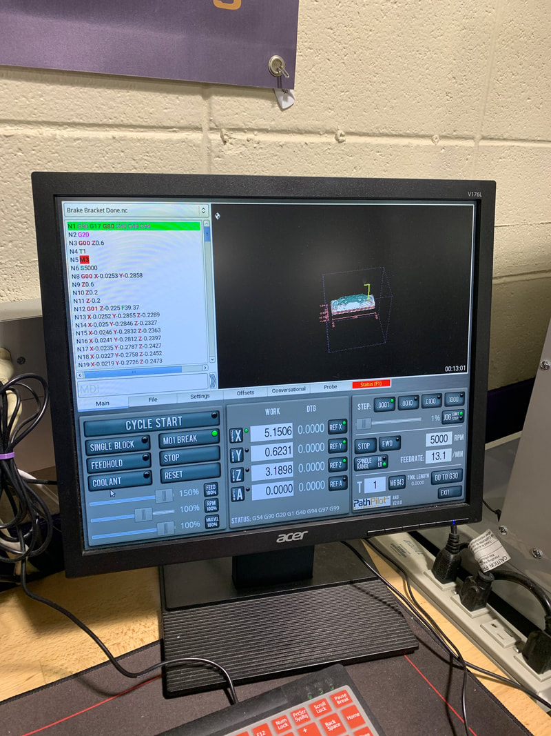
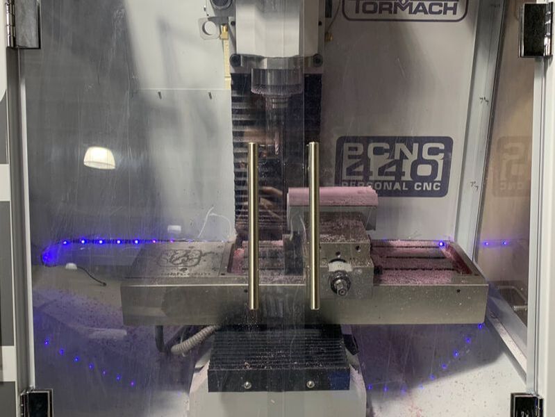
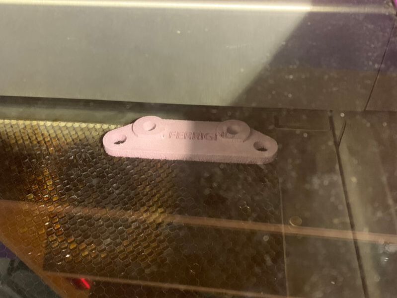
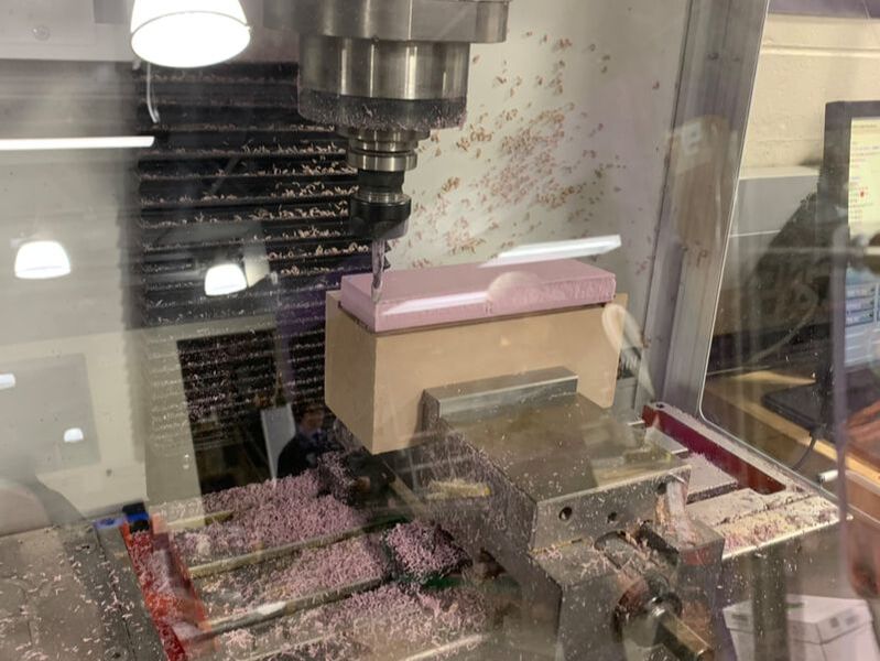
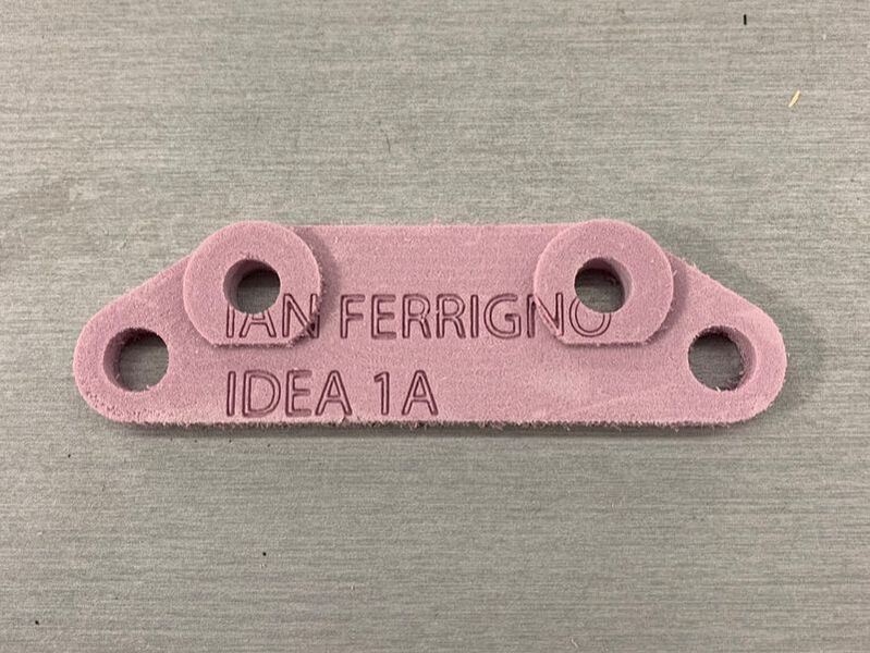
In this project we set out to create a brake bracket, which as it sounds is a part of an automobile that is part of the breaking system. We had a template design to follow and the critical piece was to ensure precise measurements in the design. The top right photo displays these measurements. Besides height and width, we had radii to create for several holes, as well as depth to consider, as the final bracket was not to be a uniform depth across the entire surface. In the top right photo you can just see holes, the outside edge radii, and the varying depth of the bracket at the top right hole. Inventor was the starting point and was where the design was finalized. The software system was attached to the milling hardware, making a seamless transition from design to production. The photos of the computer reveal the complexity of the system for making items with the mill. You can see the actual milling machine in the background of the left computer photo. The next two photos show the brake blank in the milling process, with the machine cutting away the unneeded material. The bottom two pictures show the final brake blank, and a trip through the laser machine was all it took to place the designer's name on it. |
|
|
What I LearnedAs I mentioned before, this project was a great way to see the flow of a product's creation from the design stage through milling. I noted that ensuring precise measurements was key to this brake bracket coming out useful. I learned a bit more to appreciate the use of software in the milling process as the designer has more control over precision versus in decades past when separate machines were applied to the same brake blank, which could lead to precision degredation over time.
|
|
|
Milling and Router Projects |
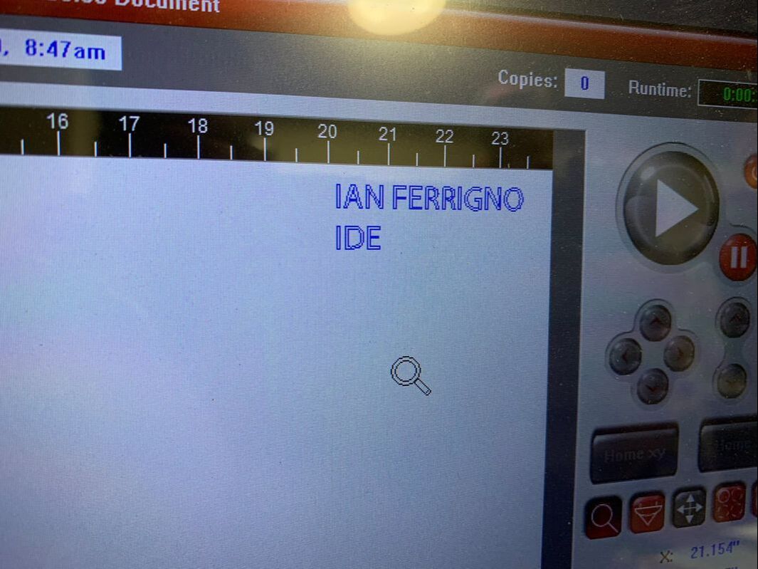
The milling and router projects required the designer's name to be laser engraved on the final product. At the right is the software set-up for the name engraving process.
|
|
